Microcontroller based Power Monitoring

This research is a continuation of several previous researches to make a power measuring instrument to support research in the laboratory. One result of these previous researches is the "Microcontroller-based Digital Wattmeter". This instrument can measure the values ​​of electrical quantities in the grid such as the frequency of the voltage, True RMS of voltage and current, power and power factor.

In this research, we add a data-logger on Digital Wattmeter so that the instrument can send all data to the computer ten times per second. We have also made a special software on the computer to receive the data. Data stored on the array in integer format. A special algorithm will make  a chart of the value of the frequency of the voltage, RMS voltage, RMS current, power and power factor on a computer screen. This software can save and print data in numerical and graphical formats.


This software has been able to work properly. The results of software testing have proven that this software can be used easily, and this microcontroller-based system is ready to be used to support some researches in the laboratory.


Digital Wattmeter with Data Logger based on Microcontroller

This research is one of the researches of the roadmap “Power Grid Monitoring Based on Microcontroller”. This research has been preceded by the research with title “Measure RMS Voltages and Currents in Power Grid Based on Microcontroller”. In that research, the microcontroller ADC samples the voltage and current grid 64 times per period of the grid voltage with 8 bit data format, so that we obtain 64 instantaneous values of grid voltage and current per period. The result can measure RMS voltage from 25 V to 250 V at frequency from 22 Hz to 80 Hz and current up to 5 A. To expand its ability to measure power and power factor of load, this research must add an algorithm to calculate it.
This research was done by adding three special algorithms. First algorithm will multiply each of instantaneous value of grid voltage and its corresponding current data, so that we obtain instantaneous electric power value. Second algorithm integrates all the instantaneous electric power values so that we obtain electric power value. The last algorithm computes power factor that is a comparison between the value of electric power and the product of RMS voltage and current. All calculation have been done quickly without involving floating point numbers and held on the sidelines of the sampling process.
Product of this research is a digital wattmeter that can measure frequency, RMS voltage and current, power and power factor up to 1 kVA of loads. Maximum measurement error of power and power factor is 2 %. All of those quantities are calculated ten times per second and display is updated once per second by average value of ten existing data. Next research, this microcontroller-based system should be added an algorithm for data reporting to computer, so that we can monitor all values graphically in computer screen.

Measure true-RMS of Voltage and Current Grid

Improvement of power quality is one attempt to increase the efficiency of electrical energy. One effort is by monitoring the amount of voltage and current RMS grid. The use of measuring devices such as voltmeters and ammeters used to sometimes do not give accurate results. Some measuring devices (including some digital measuring instrument) only measure the average value of which is calibrated to indicate RMS value. Determination of the true RMS value for a variety of waveforms to be done by using a true-RMS digital measuring instrument.
The use of digital measuring instrument gives the consequences of rising prices of measuring instruments must be purchased. So for the purposes of measuring RMS voltage value with a certain specification and accuracy should be used in microcontroller-based measuring instrument that we can make. For the purposes of the laboratory and further development, the instruments should be able to determine the RMS value for the wave of contaminated several harmonic components.
Implementation of voltage and current measurement based on microcontroller is done in order to the effort of monitoring and improving the quality of electric power. Thus the results of application of this research should have a great opportunity to develop a system of monitoring and improving the quality of electric power.


How it works

To be able to measure the RMS value we must:
1. determine the frequency signal
2. determine the sampling count per signal period
3. sampling the signal
4. calculate the RMS value

5. RMS value of the display update periodically (the period can be improved with precision algorithm for precision frequency generator).
 
System Block Diagram
System for measuring RMS voltage and current values are made based block diagram in Figure 1. Input signal for this system are the voltage and current on a grid. Detection of voltage and current do not use voltage and current sensors.
Most applications using current and voltage sensors. However, the use of both sensors will result in the current and voltage signals can not be analyzed again for other purposes.
 
Figure 1
Sampling Voltage and Current
One period of the voltage sampled 64 times, so for a period of electric current. So here it is necessary an algorithm to determine the period and frequency of electric voltage. Voltages and currents have the same frequency, but the determination is made ​​on the frequency ofthe voltage signal .
Sampling the voltage and current signals performed alternately as Figure 4. Thus the frequency of samples to be f = 128 × f_grid. Figure 4 is an example of sampling the grid voltage of 255 volts and the current with 500 mA amplitude of the fundamental components that contaminated by 3rd and 5th harmonic and electric current lag 11.25 degrees. Signal fed to pin ADC0 voltage and current signals fed to the ADC1 pin.
 
Figure 2
Selection bits ADC Data Used
Although the ADC has a maximum resolution of 10 bits. In this study, we use the ADC with a resolution of 8 bits. Use of 10-bit resolution will certainly provide a higher accuracy.
Instantaneous voltage and current represented by the 8 bit register ADCH of 10 bit ADC data samples that have been arranged left-adjust as Figure 3.
 
Figure 3
The system uses 8-bit ADC and sample frequency of 64 times the fundamental frequency of grid voltage. Measurement error caused by quantization error is reduced by using the oversampling and 2.5 VDC offset addition method. 

The Result
We have been able to measure the true-RMS of voltage from 10 to 250 volts and true-RMS of currents of 50mA to 1 A. Absolute error value of RMS voltage measurement below 0.5% for the range of voltage from 160 volts to 250 volts. And absolute error value of RMS current measurement below 4% for the range of currents from 200 mA to 1 A for currents slightly contaminated harmonic components. With a few suggestions for improvement, this system can be developed into the next research of the power quality measurement based on microcontroller.


click here for more information

Automatic Power Factor Correction Systems

The power factor is one of the problems in electric power quality improvement. In many cases, low power factor causes the waste of electrical energy. In large commercial and industrial sectors, usually used in a centralized system of capacitors in a room for power factor correction. However, changes in the electric power consumed by electrical equipment operated at any time require changes in the capacity of capacitors which must compensate for the inductive nature of the electrical equipment is being operated. A value system that can provide appropriate capacity of capacitors to improve power factor is needed on systems with dynamic changes in electrical load.
Ideally, all customers of electric energy should have a good power factor (close to the value 1) to reduce the cost of electrical energy production. However, power factor corrections should be done the right way for any equipment used. This raises a new problem: how to design a power factor correction systems that can be used for all electrical equipment used. And how for power factor correction systems can also be operated for a variety of electrical load, so it does not need to be plugged at any existing electrical equipment. With this system, the expected power factor can be fixed easily and the system can be used for every electricity customer. With the corrected power factor, the electricity companies no longer must be generated electrical energy that is greater than the needs of customers.
Power factor is one parameter determining the quality of electric power. A good quality electrical power will increase efficiency in the electricity system. With the same production at the customer side, the total electrical energy consumed by customers will be reduced. This will be followed by a decrease in the voltage loss in the distribution system, thus decreasing the voltage drop on the customer side. On the generation of electrical energy, without reducing the electrical energy dollars are sold, the total energy generated will be smaller so that the operational costs of electricity generation will be reduced. With the increased efficiency of electric power, rising power demand next few years can still be supplied by the current generator, so the electricity deficit in this country for a while can be forgotten and needs additional power plant may be delayed.


Using ATmega8535 AVR Microcontroller
Heaviest Electrical Loads for the System 
Modeling using MATLAB
The Performance of the APFC

Using ATmega8535 AVR Microcontroller

APFC system uses AVR microcontroller family as the main component that has an internal ADC. ATmega8535 microcontroller is used here. To be able to record voltage and current signals, we use a voltage-to-voltage converter and current-to-voltage. A signal conditioning is used to make the both output signal voltage of the converter in accordance with the characteristics of the ADC inputs. This system uses a capacitor bank (C-bank), which consists of four capacitors. These capacitors are used for power factor correction.


The need for Automatic Power Factor Correction (APFC) Systems
Heaviest Electrical Loads for the System  

Modeling using MATLAB
The Performance of the APFC

Heaviest Electrical Loads for the System

For this system, the greater the power used, effort should be made for power factor correction is also more severe. Capacitor capacity value should be used for power factor correction will be even greater.
At the same apparent power, the lower the power factor, power factor correction efforts are also increasingly heavy. Attempts to raise the power factor will require a capacitor with larger capacity as well. Low power factor due to the large value of phase difference between voltage and current.
Heaviest electrical loads for the system occurs when the load has largest apparent power and smallest power factor. All capacitors in the C-bank should be able to correct this condition so that the value of power factor becomes one.
Modeling using MATLAB
This model is created using Simulink in MATLAB version 6.5.1. Models of automatic power factor correction systems can be seen in the following figure. This model consists of several subsystems and the S-Function. This system is also equipped with input devices that can retrieve data from a file and the output device (data logger), which can save data to multiple variables in a workspace that can be saved to a file for further processing. Listing program written in C language.


The need for Automatic Power Factor Correction (APFC) Systems
Using ATmega8535 AVR Microcontroller
Modeling using MATLAB
The Performance of the APFC


Modeling using MATLAB

This model is created using Simulink in MATLAB version 6.5.1. Models of automatic power factor correction systems can be seen in the following figure. This model consists of several subsystems and the S-Function. This system is also equipped with input devices that can retrieve data from a file and the output device (data logger), which can save data to multiple variables in a workspace that can be saved to a file for further processing. Listing program written in C language.


The need for Automatic Power Factor Correction (APFC) Systems
Using ATmega8535 AVR Microcontroller
Heaviest Electrical Loads for the System 
The Performance of the APFC

The Performance of the APFC

Assuming the capacitor value of automatic power factor correction systems can be any, or in other words the number of variations of the value of the capacitor capacity is infinite, the higher the apparent power of load or the lower the power factor of load, power factor correction efforts will be heavier and value output power factor can still be worth far below one.
But with the limited number of variations in the value of the capacitor capacity, as long as the maximum limits of correction, the higher the load apparent power, power factor corrected values would be guaranteed getting closer to one and have a fairly small fluctuations.
In order to achieve the value of power factor as close to one, the determination of the total capacity of capacitors in the C-bank should be based on the largest electrical load that happens, both electrical load with the greatest apparent power and the smallest power factor, and not based on installed power capacity.
In conditions with heavier loads than specified, the system will perform power factor correction by using all of available capacitors and there is the possibility of power factor corrected still much smaller than one.
With the same power factor value, the lower the load apparent power, power factor corrected values will be more varied and this value can be far below the value of one. The low power factor at low power will not be harmful because the reactive current that occurred only a little.
The model has been developed can be implemented into a prototype of automatic power factor correction that can be used for many consumers.
For overall power factor correction, should be considered the harmonic components. This research can proceed with efforts to correcting harmonic component.


The need for Automatic Power Factor Correction (APFC) Systems
Using ATmega8535 AVR Microcontroller
Heaviest Electrical Loads for the System 
Modeling using MATLAB

Measure the Frequency of Grid Voltage and Phase Difference between Current of Load and Grid Voltage


Voltage range     : 40 V ~ 280 V (Vrms)
Current range     : 0 ~ 200 mA
Frequency          : 35Hz ~ 70Hz
Phase differnece : 0° ~ 90° (lead or lag)


        Voltage grid should be is 50Hz or 60Hz. But in reality the frequency of the grid are sometimes shifted slightly, so be below or above 50Hz or 60Hz. The stability of the voltage frequency is one indicator of the quality of electrical voltage. The stability of the power grid's frequency is a health indicator of the grid's ability to respond to changes in supply and demand of electricity. Although there are other grid characteristics that can be measured,
frequency is less affected by local disturbances than other attributes like voltage and current.

       As we develop more energy resources, these resources need to be integrated efficiently and cost effectively with our existing energy infrastructure – the power grids. Alternating Current, or AC, power generators need to be synchronized to provide optimal service and electric energy supply. When we consume electricity, we place a load on the power grid. We can develop smart appliances that can measure the grid's frequency and the health of the grid's power supply; then respond appropriately by scheduling or reducing load to help maintain grid stability.
      Most of the electrical load current draw currents that have a different phase with the voltage supplied to him. Current on inductive load is lagging behind the voltage. Current on incandescent sometimes precedes the voltage of grid. Fact, the current in the electrical load that use of switching power supply is extremely precede the voltage.
      In order to achieve maximum efficiency in electricity usage, the phase angle between the currents must be equal to the voltage, in other words, the current must be in phase with voltage. Real power comparison of voltage multiplied by current is called the power factor.
Ideally, power factor of load is to be one.
      Measuring instrument of real power and power factor both analog and digital has been widely available. However, a measurement to the phase difference between voltage and current flowing in the grid is still rarely found. The need for these measuring devices in the lab sometimes still constrained. This paper describes the results of the implementation of the ATmega8535 microcontroller as a major component of the device for measure the frequency of the grid voltage and measure the phase difference between voltage and current flowing in the load. Furthermore, the expected applications can be developed for the measurement of the values of voltage and current RMS, power and power factor, even down to the power analyzer  based microcontroller.
Programs in this microcontroller can be applied to several other AVR microcontroller series if this program will not be developed further.

The Need for Phase Difference Measuring Instrument
Measure the Frequency of Grid Voltage rather than Measure the Frequency of Current
Voltage and Current Converter
The Signal Conditioning
The use of the microcontroller ADC
Frequency Measurement
Phase Difference Measurement
Output Display Format

click here for more information

Measure the Frequency of Grid Voltage rather than Measure the Frequency of Current


      The fundamental frequency of the current flowing to a load will be the same to the fundamental frequency of the voltage supplied to it. Due to the current usually have more harmonic components than voltage, frequency measurement easier done on the voltage supplied to it.
      The frequency of the grid voltage in Indonesia is 50 Hz, whereas in some other countries is 60 Hz. To reduce the calculation errors caused by harmonic components, frequency range of the measurement values can be restricted so that the harmonic frequencies will be ignored. To increase accuracy, measurements of the frequency value for the low frequency signal, is done by first measuring the value of the period, and not by counting the occurrence of waves. Nevertheless, the accuracy of the measurement result is displayed in the format of three digits such as the frequency measuring instruments for grid voltage.
best to avoid using voltage and current sensors
      Detection of voltage and current values does not use a voltage and current sensor. Generally, the voltage and current signal was converted to DC voltage signals by a sensor and then fed to the ADC input. But this will make the voltage and current cannot be analyzed further more.
      In this application, the value of alternating voltage which has been normalized is fed directly to the ADC input of the microcontroller. Current can be detected by the ADC after converted into a voltage. 


The Need for Phase Difference Measuring Instrument  
Measure the Frequency of Grid Voltage rather than Measure the Frequency of Current
Voltage and Current Converter
The Signal Conditioning
The use of the microcontroller ADC
Frequency Measurement
Phase Difference Measurement
Output Display Format

Voltage and Current Converter

Voltage-to-Voltage Converter:
                  Input                      Output
Vrms      0 ~ 280V        0.57 ~ 1.77V with 5VDC offset or
Vpp        0 ~ 400V        0.80 ~ 5.00V with 5VDC offset

Current-to-Voltage Converter:
                  Input                      Output
Irms      0 ~ 500mA      0.00 ~ 1.77V with 5VDC offset

      In order for the grid voltage and current flowing in the load can be read by the ADC microcontroller, voltage signal are converted using a voltage-to-voltage converter that is step-down transformer. While the current signal converted using current-to-voltage converter that is a step-up transformer which has very low inductance at primary coil and high inductance at secondary coil. For this purpose, we can use the adapter transformer. In this case, I_out and I_in fed to the low voltage coil and we get v0 and ground from high voltage coil as Figure 1.

Figure 1
      At the ADC input of microcontroller, we found clipper diode that can be utilized as a main component to build a zero cross detector that can be used to measure the period of input voltage. But in this study, the input voltage that is usually sinusoidal form will be entered as a whole, so that in future this system can be developed for the calculation of RMS values and power.

The Need for Phase Difference Measuring Instrument
Measure the Frequency of Grid Voltage rather than Measure the Frequency of Current

The Signal Conditioning
The use of the microcontroller ADC
Frequency Measurement
Phase Difference Measurement
Output Display Format

The Signal Conditioning


      v0 and v1 fed into the Signal_Conditioning block to have normalized so that the maximum voltage is Vpp = 5V. In this block, we add 2.5 V DC offset voltage to both signal so they have a voltage range of 0 to 5 V according to the ADC limits.
      The phase shift will occur while converting grid voltage to low voltage and converting current to voltage. To compensate them, on the block Signal_Conditioning, there is the phase shifting circuit that will adjust the phase again. This circuit also functions as a first-orde high-pass-filter. These filters are used to reduce the amplitude values of harmonic components which might make the calculation value of the frequency and phase difference to be wrong.
     The output of this block is a voltage signal v0' that it’s shape like the grid voltage, and voltage signals v1' it’s shape like the current grid. Phase shift between v0' and v1' equal to the phase shift between voltage and current grid.


The Need for Phase Difference Measuring Instrument
Measure the Frequency of Grid Voltage rather than Measure the Frequency of Current
Voltage and Current Converter

The use of the microcontroller ADC
Frequency Measurement
Phase Difference Measurement
Output Display Format

The use of the microcontroller ADC


     v0' fed to the input channel 0 of the ADC, while v1' fed to the second channel of the ADC input. Another channel ADC inputs are connected to the Ground to reduce the effects of cross-talk between the two entries. Voltage signal v0’ which represent the grid voltage and signal voltage v1’ which represent the load current, sampled by the ADC of microcontroller.
     The higher the ADC clock, so sampling process will be faster, but tend to diminish the accuracy of the ADC. In order to obtain fast conversion time but the accuracy of eight bits, then the ADC is run with prescaler = 16. This means that the ADC is run using a clock frequency of 691 kHz. Time to do a conversion or the conversion period (tc) is 14 times the clock period or about 20 microseconds. At 50 Hz input signal, sampling the voltage signal at intervals of 20 microseconds will provide a maximum error 0.1%


The Need for Phase Difference Measuring Instrument
Measure the Frequency of Grid Voltage rather than Measure the Frequency of Current
Voltage and Current Converter
The Signal Conditioning
Frequency Measurement
Phase Difference Measurement
Output Display Format

Frequency Measurement


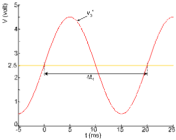
     Measurement of the frequency of the grid voltage is done by first measuring the time between two successive foot of the mountain, as Figure 2. At the time of the grid voltage moves up above 2.5 V, a timer is run in normal mode. And when the value of grid voltage moves up on the 2.5 V anymore, timer 1 is stopped.  Timer 1 run during Δt1.
 
Figure 2
     Timer 1 is 16-bit timers. This timer is operated with prescaler = 8. Time for counting one digit is tT1 = 0.723 microsecond. The result of count is 16 bit hexadecimal value stored in a register TCNT1 that formed by pairing 8-bit registers TCNT1H and TCNT1L.
For 50 Hz input signal, the counting result is 6C00h. To avoid detection of the harmonic frequency, the frequency restricted from 35 Hz to 70 Hz. So that, the valid value of TCNT1 is from 9A49h until 4D24h. Maximum error of this counting is 0.004%.


The Need for Phase Difference Measuring Instrument
Measure the Frequency of Grid Voltage rather than Measure the Frequency of Current
Voltage and Current Converter
The Signal Conditioning
The use of the microcontroller ADC
Phase Difference Measurement
Output Display Format